Hey there, if you’re an internal ring gear supplier like me, you know that nailing the tooth profile is make or break for your parts. Mess that up, and you end up with noisy transmissions, premature wear, or even gear failure—nothing kills a customer relationship faster than a batch of bad parts. I’ve been in this game for 12 years, and I’ve tested every trick in the book to measure internal ring gear tooth profiles accurately (and avoid the headaches that come with guesswork). Today, I’m breaking down exactly what we do at our shop to get this right, no fancy lab degree required.
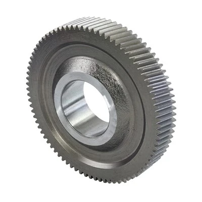
First, let’s get on the same page: what even is an internal ring gear? It’s that circular gear with teeth that curve inward, right? They’re the unsung heroes in transfer cases, oil pumps, and motorcycle transmissions—stuff you use every day, even if you don’t notice them. For us, getting their profile right is non-negotiable because they mesh with external gears, and any tiny deviation can throw off the entire system. Let’s start with why measuring this is tricky. Unlike external gears, you can’t just roll a pin or a caliper around the outside easily—you’re working inside a hollow ring, so access is limited. Plus, their involute profile (that curved shape that makes smooth meshing possible) has to be perfect to avoid friction. Over the years, we’ve upgraded from old-school tools to more precise setups, and along the way, we’ve picked up a few hacks that save us time and money.
Let’s start with the basics: the key specs we need to measure. For internal ring gears, it’s not just the size of the teeth. We’re talking about involute profile deviation (how far the actual tooth curve is from the ideal design), pitch diameter (the point where the gear meshes perfectly with a pinion), tooth thickness (the space between teeth at a certain point), and runout (how much the gear wobbles when it spins). If any of these are off, the gear won’t mesh smoothly, and that’s a fast track to customer returns.
Now, the tools we use. Back in the day, we used a coordinate measuring machine (CMM), but it’s clunky for small to medium batch runs, and it’s slow. Then we switched to a gear measuring center, which is a game-changer but also pricey. But we also use some more accessible tools for quick checks when we’re setting up a new production run or verifying a small order. Let’s walk through the step-by-step process we follow every time.
First step: prep the part. You can’t measure a dirty gear. We blast our ring gears with compressed air to get rid of metal shavings, then wipe them down with a lint-free cloth. If there’s any grease from machining, we hit it with a little degreaser— residue will throw off measurements, especially for tooth thickness. Also, we mount the gear securely on a fixture that centers it perfectly; if it’s off-center, all our profile measurements will be wrong. For that, we use a precision arbor that fits the gear’s inner bore, since that’s our reference point. No wiggling allowed here.
Second step: measuring involute profile. This is the big one. The involute curve is what lets gears roll against each other without slipping, so if that’s distorted, you get noise and wear. For this, our go-to is a gear measuring center. It has a probe that moves along the tooth surface, tracing the curve and comparing it to the CAD model we have for the gear. But for quick checks, we use involute measuring pins—two small cylindrical pins that fit between two teeth, and we measure the distance across them. Wait, no, that’s for pitch diameter, but we also use a profile projector for small batch runs. It projects a magnified image of the tooth onto a screen where we’ve got the ideal involute outline drawn, so we can line them up and see if there’s any gap. That’s way faster than the gear measuring center for small orders, though it’s a little less precise.
One thing I’ve learned the hard way: when measuring internal teeth, you have to make sure your probe can reach all the way down the tooth. The tip of the tooth profile—near the top of the internal curve— is a common blind spot. If your probe doesn’t go deep enough, you’ll miss deviation there. We once had a batch where the top 10% of the teeth were slightly flattened, and we only caught it when we upgraded our probe to a longer, thinner one. That saved us from sending out bad parts that would’ve failed in a customer’s transfer case (you can check out the kind of gears we supply, like transfer case pinion gears, to see how critical this matching is: /gear/transfer-case-pinion.html).
Third step: checking pitch diameter and tooth thickness. Pitch diameter is the circle where the teeth would mesh with another gear, and for internal ring gears, it’s measured using those involute pins I mentioned. The formula is a bit specific for internal teeth—you calculate the distance over two pins, adjust for the pin size, and you get the pitch diameter. For tooth thickness, we use a gear tooth caliper, but again, internal teeth mean the caliper has to reach inside. We use digital gear calipers that have long, thin jaws for this. The thickness has to match the design by a few thousandths of an inch, otherwise, there’s too much play (causing noise) or not enough (causing binding). We’ve messed this up before with a motorcycle transmission gear batch, and the customer had to recall some units—never again. That’s why we double-check this with the gear measuring center every time we do a production run: /gear/motorcycle-transmission-gear.html.
Fourth step: runout and alignment. Runout is how much the gear spins off-center when mounted, and for internal ring gears, this affects how the teeth mesh. We use a dial indicator for this: mount the gear on the arbor, spin it slowly, and watch the indicator. If it varies more than, say, 0.001 inches, we have to check the fixture or the gear’s inner bore. Misalignment here is a killer because even perfect tooth profiles won’t work if the gear is wobbling.
Now, common mistakes to avoid. Number one: not accounting for the internal geometry. A lot of new guys in our shop try to use external gear measuring methods on internal ones, and that’s where they go wrong. The involute is inverted, so the measurement points are reversed. Number two: not calibrating tools regularly. Our gear measuring center gets calibrated every month, and the profile projector is checked with a master gear every week. Even a tiny calibration error can throw off hundreds of parts. Number three: rushing through prep. I’ve seen guys skip the degreasing step because they’re in a hurry, and oil on the teeth makes the probe slip, leading to bad data. Take your time here— it’s worth it.
Also, when we’re testing new materials or processes, we cross-check. For example, if we switch to a new CNC milling gear setup (/gear/cnc-milling-gears.html) for our internal rings, we’ll run a few trial parts, measure them with both the gear center and the profile projector, and make sure the profiles line up. That way, we don’t have to shut down production if there’s a small adjustment needed. For oil pump gears, which use internal rings to move fluid, profile deviation can cause leakage, so we’re extra strict here (/gear/oil-pump-gear.html).
At the end of the day, the goal is to make sure every internal ring gear we ship meets or exceeds the customer’s specs. We keep a log of every measurement for each batch, so if a customer has an issue, we can go back and check exactly what we measured. It’s saved us a ton of time in troubleshooting, and customers love that transparency.
If you’re an engineer or a procurement person looking for reliable internal ring gears that meet strict profile standards, hit us up. We’ve got years of experience perfecting this process, and we work with all kinds of industries— from automotive to small engine components. Don’t settle for parts that might have hidden profile issues. Reach out, and we can talk through your specific needs.
References


- American Gear Manufacturers Association (AGMA) Standard 2015-A01: Gear Tooth Quality Measurement
- Gear Technology Magazine, "Measuring Internal Gear Profiles: Best Practices for Production"
- ISO 1328-1:2013, Cylindrical Gears - ISO System of Flank Tolerance Classification - Part 1: Definitions and Allowable Values for Deviations of Flanks and Helix Deviations